About the Hiraga Crossover Circuit
The following discussion is about the basic 2-way high performance Hiraga circuit crossovers available Pete Riggle Audio Engineering.
Also available are Hiraga circuit crossovers including a supertweeter circuit allowing direct connection and control of supertweeter. You can check these out at the following link: Owner's Manual, Hiraga Circuit with Supertweeter Circuit Option
The Hiraga crossover circuit of interest was designed by Jean Hiraga for use with a pair of Altec Lansing A5 loudspeakers he famously showed in his Paris salon. I obtained the circuit from the Jon Stronczer article, and decided to try the crossover circuit on my Altec Lansing A7 loudspeakers. I liked the result, finding the frequency response provided by the circuit to provide a nice full midbass which adds to the loveliness of these speakers. The circuit also provides a rising high end above 10 kHz which helps the tweeters out at the top end where they roll off around 12 kHz. The circuit is second order, crossing over at 585 Hz, with a notch filter creating a dip of about 4 dB at about 3500 Hz, which can compensate for excessive sensitivity of the tweeter horn in the middle of its band, and can diminish harshness in this range that sometimes plagues recorded music, particularly on massed strings and massed vocals.
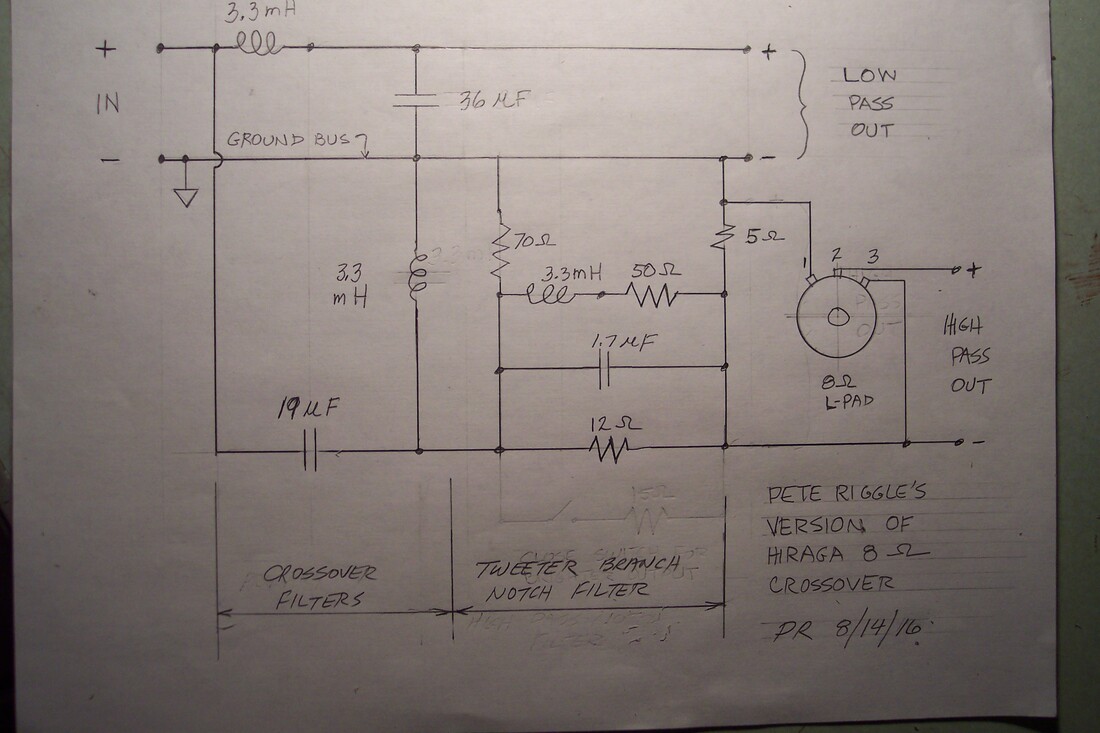
Here is the crossover circuit for the 8 ohm Hiraga circuit, with an L-pad added tor control of tweeter output. For a 16 ohm version one would double the inductor, resistor, and L-pad values and halve the capacitor values.
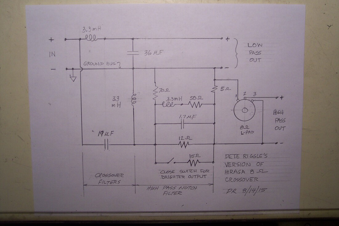
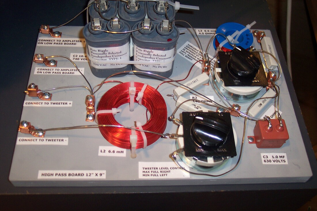
The next image shows the circuit that I built for myself and still have in use after quite a few years. Note the 15 Ohm resistor is switchable to be in parallel with the 12 Ohm notch filter resistor. The combined resistance of 15 Ohms in parallel with 12 Ohms is 6.67 Ohms. Switching this resistor into the circuit eliminates the Hiraga notch, giving a brighter sound.
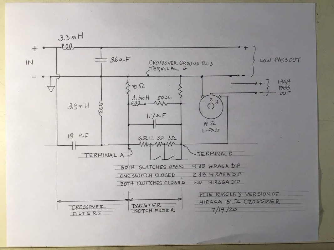
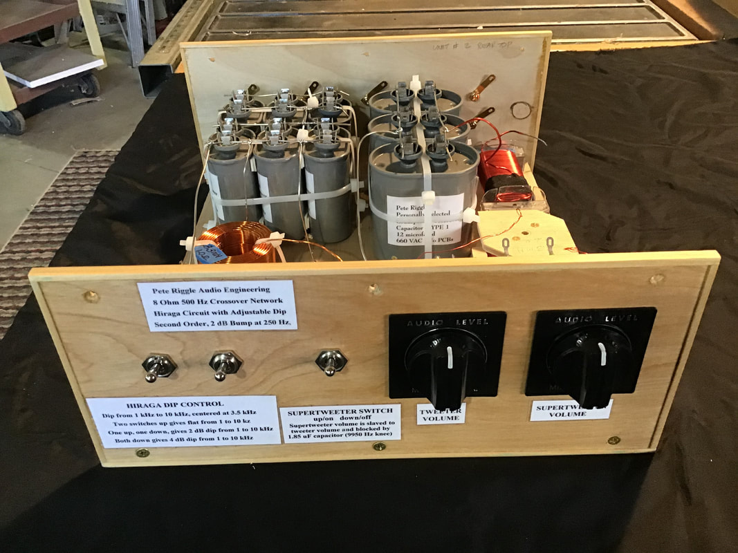
The next image shows the Hiraga based circuit that I currently build for my customers. Switches allow the notch filter resistance to be set at 6, 9, and 12 Ohms. With 6 Ohms resistance the response curve is flat between 800 Hz and 9 kHz. With 9 Ohms resistance the Hiraga notch is 2 dB deep. With 12 Ohms resistance the Hiraga notch is 4 dB deep.
Supertweeter Circuit Option
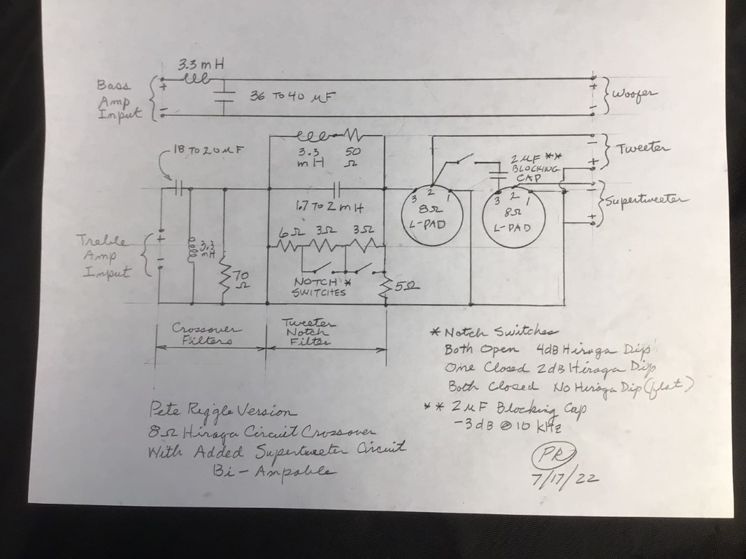
Important Note: The circuit diagram below shows the supertweeter piggy-backed off of the tweeter. The idea behind this arrangement is that the user would adjust the supertweeter relative to the tweeter, after which adjusting the tweeter level would handle the entire treble adjustment. This was a reasonable idea, but I have found that the supertweeter sounds clearer if it is driven directly from the amplifier + input of a single amplifier crossover or driven from the treble amplifier + input of a biampable crossover. Until I make time to publish a modified circuit diagram, here is the change that is needed: Disconnect the supertweeter switch from terminal 2 of the tweeter L-pad and reconnect the switch to the power amplifier + input of the crossover for a single amplifer installation, or to the treble power amplifier + input of a biampable crossover.
For customers who wish to use a capacitor blocked supertweeter in conjunction with their 2 way speakers, I can provide a crossover with the circuit shown below. The tweeter control L-pad adjusts the tweeter relative to the woofer. The supertweeter is piggy-backed off the tweeter, with its own L-pad to adjust the supertweeter relative to the woofer. A switch allows the user to enable or disable the supertweeter and its L-pad.
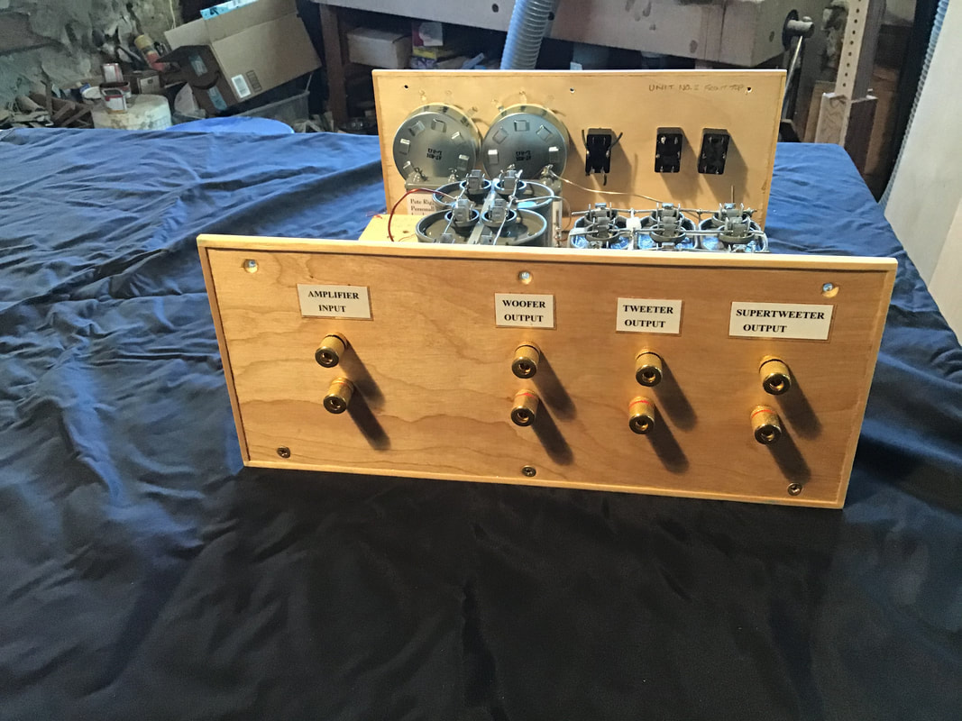
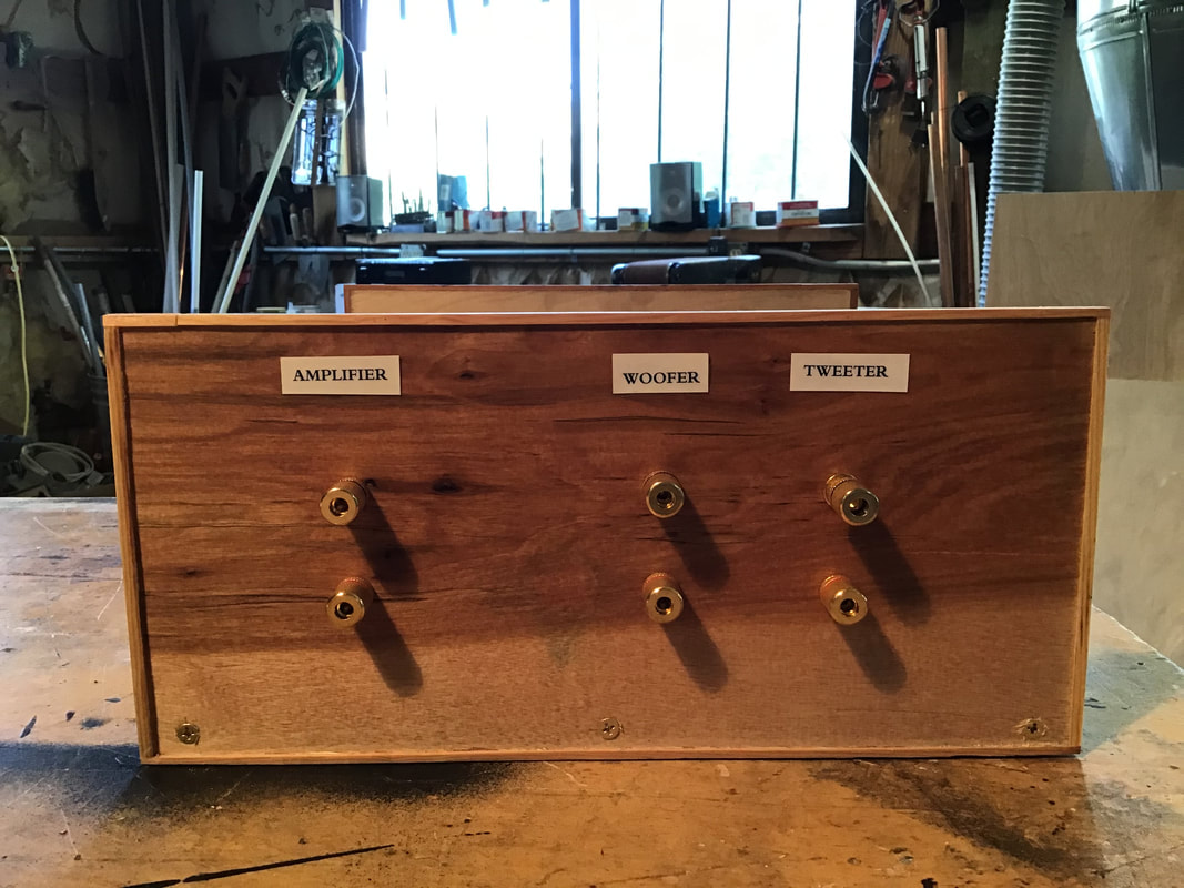
The front and rear panels of a Hiraga Circuit Crossover with the supertweeter circuit option are shown below. The rear panel image shows one set of amplifier inputs. The current versions of my Hiraga and Altec N800 crossovers provide two sets of amplifier inputs, one for the low pass filter, and one for the high pass filter, to allow bi-amping. If only one amplifier is to be used, the two sets of inputs can be strapped together with straps provided.
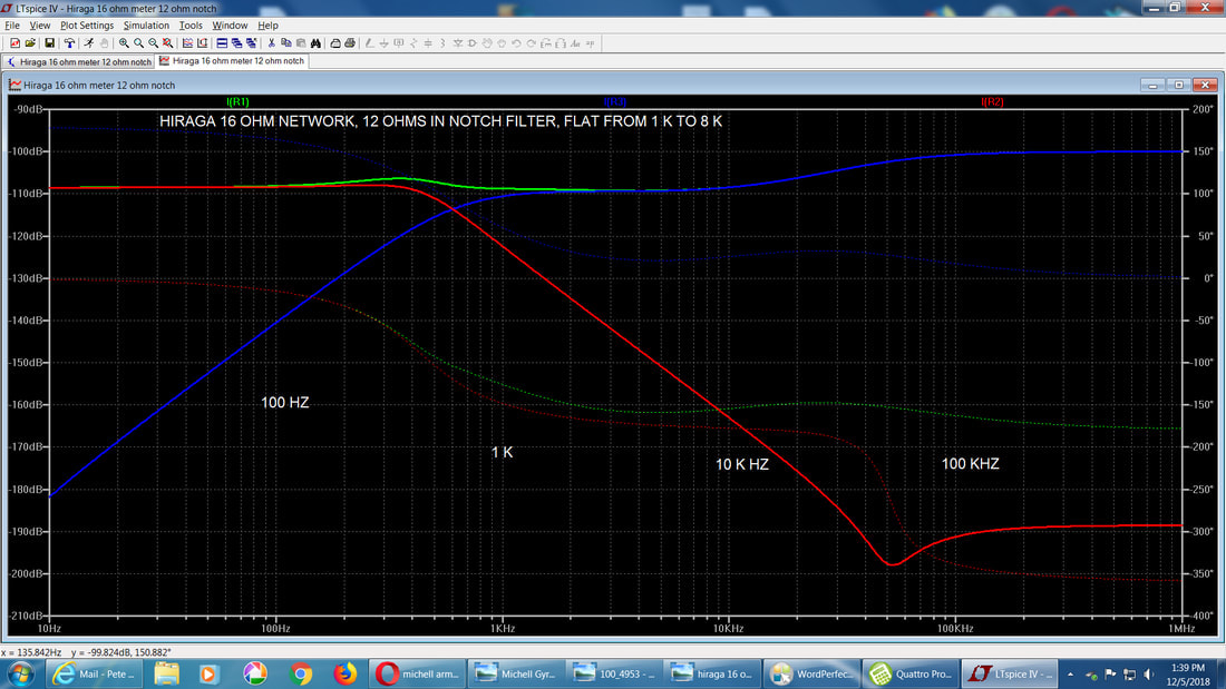
Hiraga Crossover Electric Response Curves Calculated with the SPICE Circuit Analysis Program:
I have used the SPICE circuit analysis program to calculate electrical response curves for an 8 or 16 Ohm Hiraga circuit with corresponding constant resistance loads. An adjustment has been made make correct for the imbalance in sensitivity between the woofer and the tweeter. This makes the response curves look like anechoic response curves for a loudspeaker with perfect drivers, time aligned and concentric, with no baffle or room effects, and with the tweeter sensitivity adjusted for compatibility with the woofer. In the real world the tweeter is adjusted by ear with an L-pad to bring its sensitivity into accord with the woofer sensitivity.
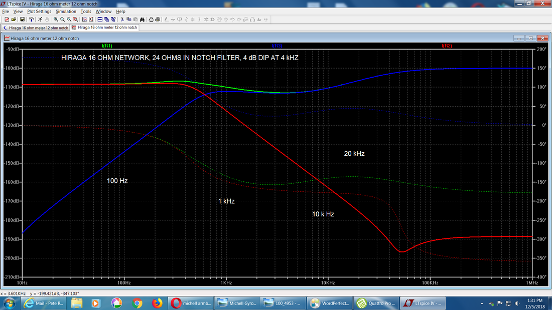
The figure below shows the electrical response curve with the switches set up for the Hiraga 4 dB dip. Notice that the dip is wide, beginning at about 1 kHz and ending about 10 kHz, reaching -4dB at about 3500 Hz. Notice the rising response above 10 kHz which helps to offset the falling response of the tweeter horn above 10 kHz.
The red curve is the woofer response. The blue curve is the tweeter response. The green curve is the combined response. It is characteristic of second order crossovers to have a 3 dB hump in the response at the crossover frequency. A Butterworth second circuit would locate the hump at the 580 Hz crossover frequency. The Hiraga circuit locates the hump at 340 Hz, which slightly warms the midbass. Note the 4 dB dip at 3500 Hz, and the rising response above 10 kHz.
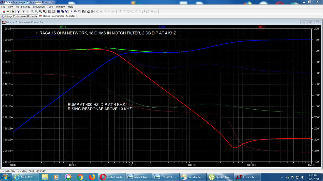
Here is the response curve with the switches set for a 2 dB dip at 3500 Hz.
Here is the response curve with the switches set for a 2 dB dip at 3500 Hz.
And here we have the switches set to eliminate the 3.5 kHz dip.
Below are images of Hiraga circuit crossovers with fancy front and rear panels. The front and rear panels are 1/4" thick plywood. The tweeter Lpad control is on the front panel.
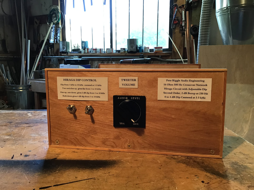
The following image shows a Hiraga circuit crossover front panel. The switches that control the Hiraga dip are to the left of the tweeter L-pad control. The front and rear panels provide a convenient place to mount the controls and the terminals.
The following image shows a Hiraga circuit crossover front panel. The switches that control the Hiraga dip are to the left of the tweeter L-pad control. The front and rear panels provide a convenient place to mount the controls and the terminals.
Fancy Covers
The construction of the crossovers makes it convenient to provide fancy covers which enclose the sides and top of the crossover. Two cover options are available, priced at $300 per pair. Plans are available at no cost for the DIY woodworker wishing to build the covers.
Cover top and sides, Option 1:
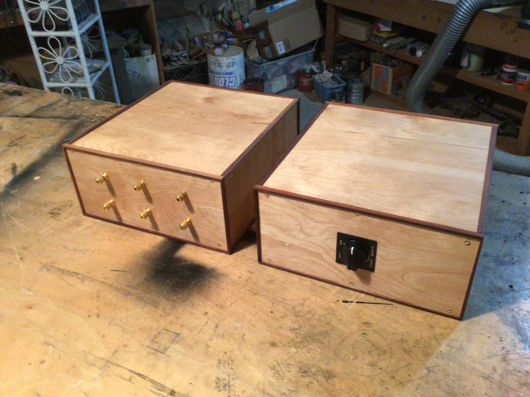
For this option the top and sides are 3/16 in hardwood veneered plywood, with 3/4 inch cleats joining the tops and sides at the corners. The photo below shows crossover cabinets with this option for the covers. These are cabinets for the Altec N800F circuit crossovers, before the labels have been applied.
Cover sides and top , Option 2:
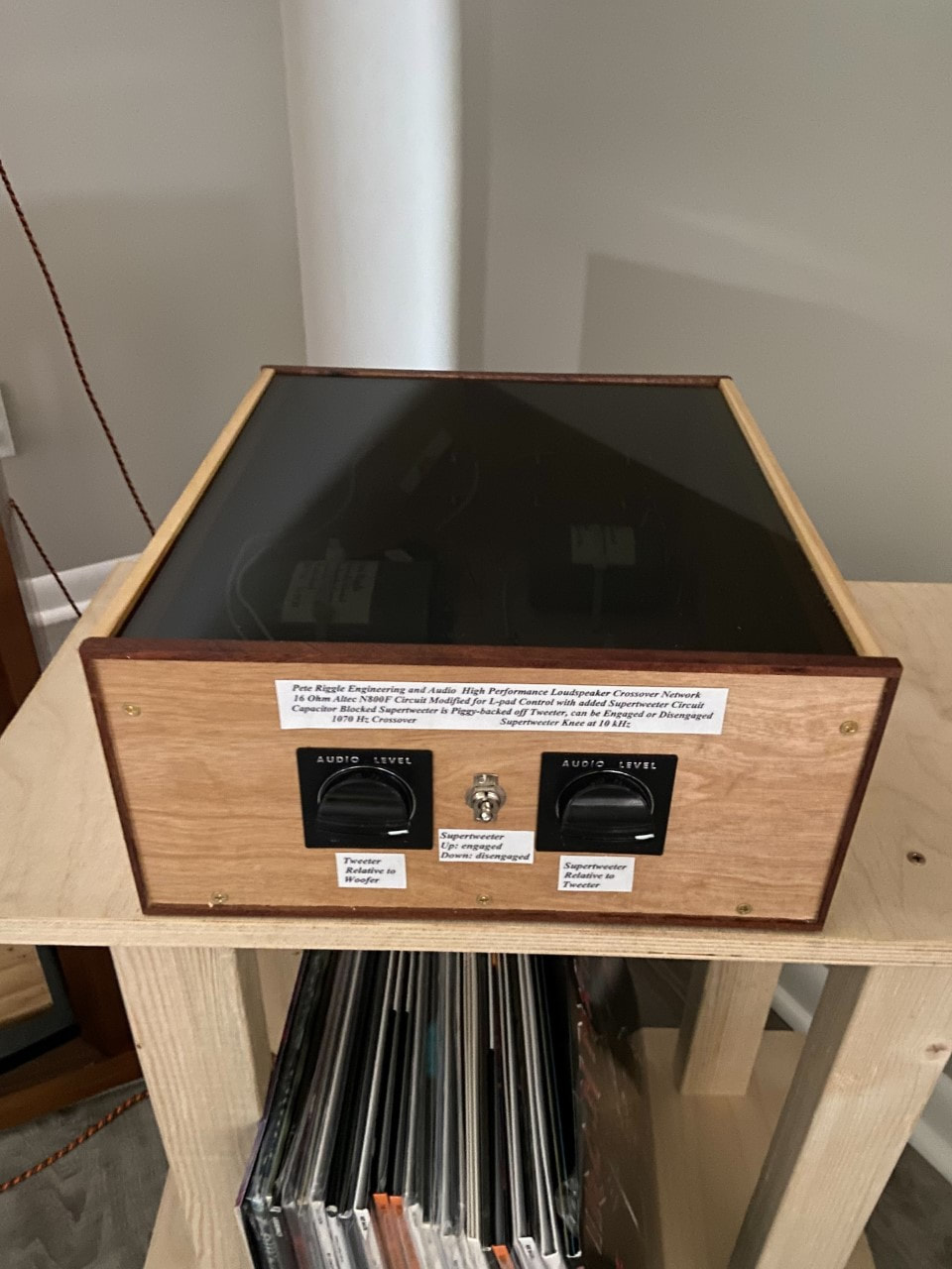
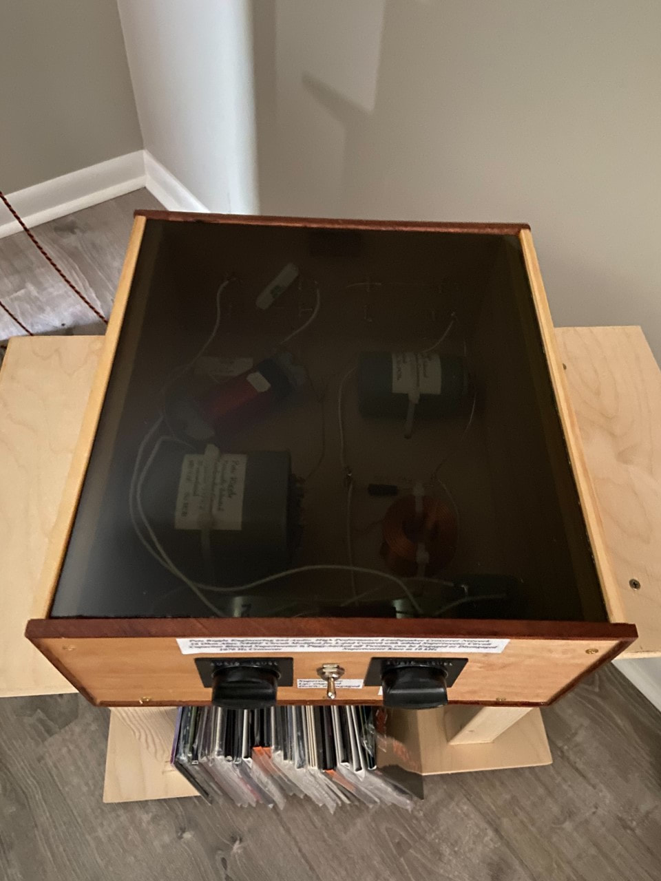
Option 2 for covers uses hardwood sides with a cast acrylic cover. The cover can be smoked cast acrylic, gloss black cast acrylic, or clear cast acrylic. The hardwood is selected to match the veneer of the front and rear panels. See the photos immediately below, which happen to be for Altec N800 circuit crossovers.
Option 2 for covers uses hardwood sides with a cast acrylic cover. The cover can be smoked cast acrylic, gloss black cast acrylic, or clear cast acrylic. The hardwood is selected to match the veneer of the front and rear panels. See the photos immediately below, which happen to be for Altec N800 circuit crossovers.
Interior Construction
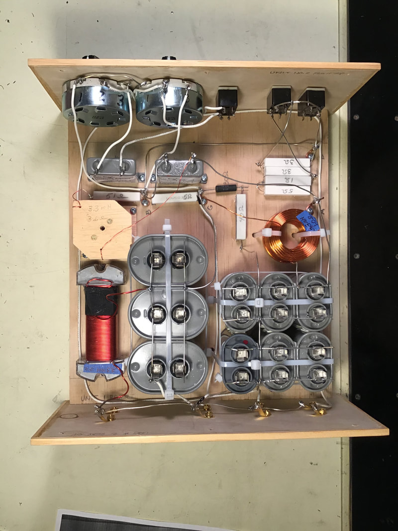
The interior construction of one of my crossover networks is shown below. This is for a Hiraga network crossover including the capacitor blocked supertweeter circuit option.
The interior construction of one of my crossover networks is shown below. This is for a Hiraga network crossover including the capacitor blocked supertweeter circuit option.
Early Efforts (DIY Interests):
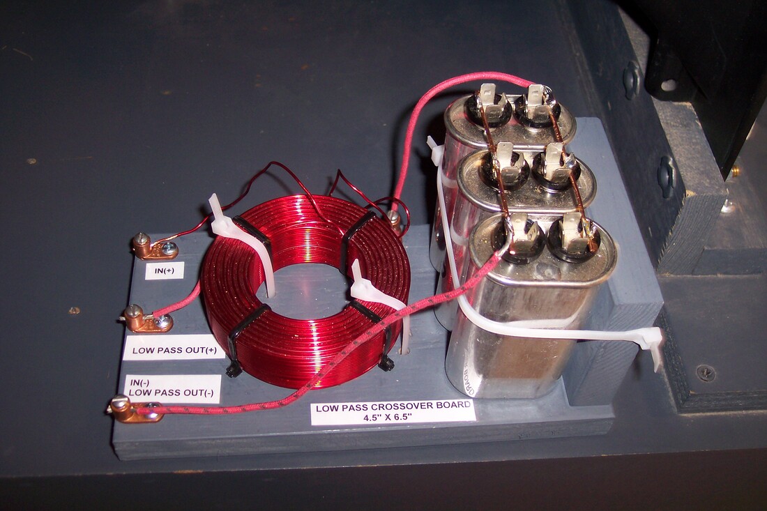
For DIY hobbyists I have included the following images showing what I was doing
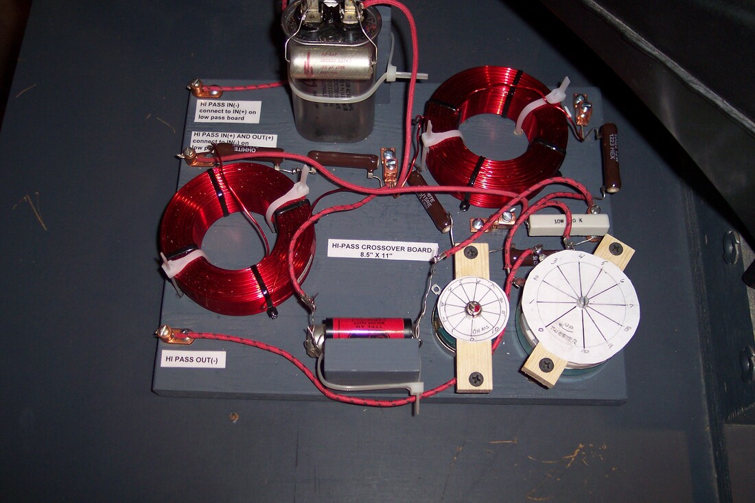
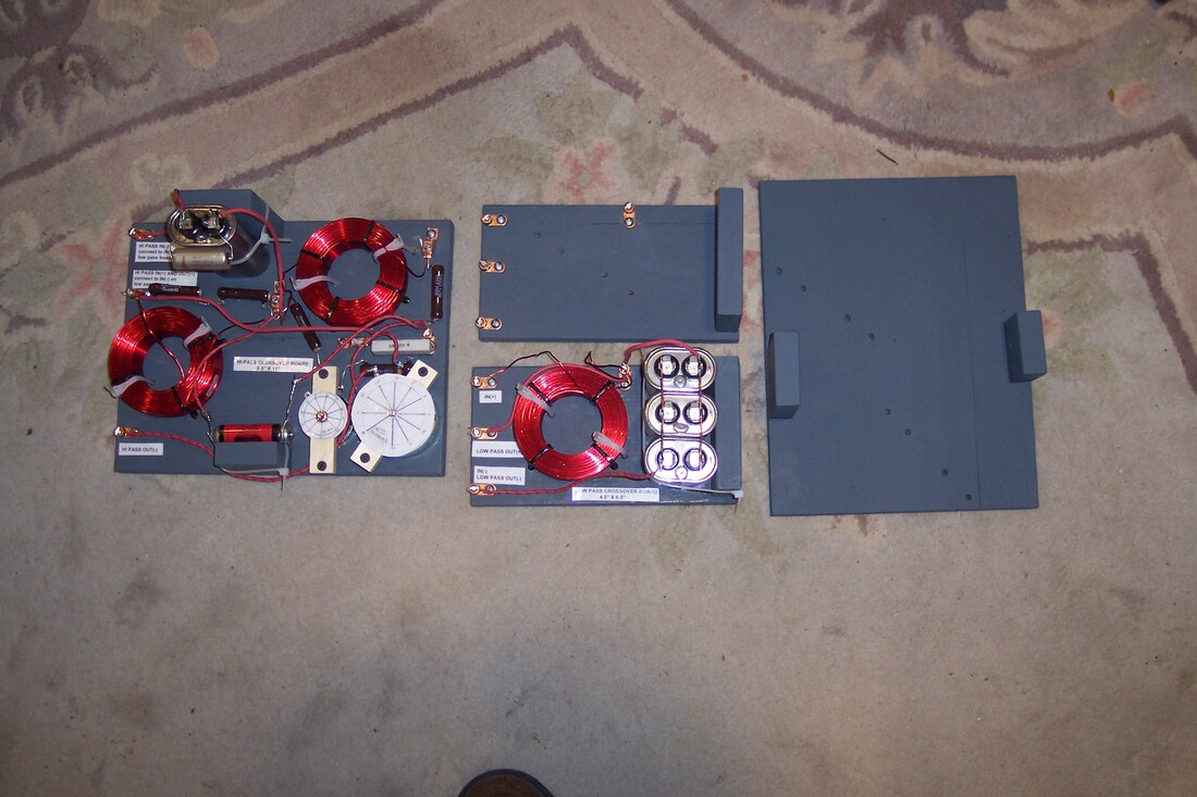
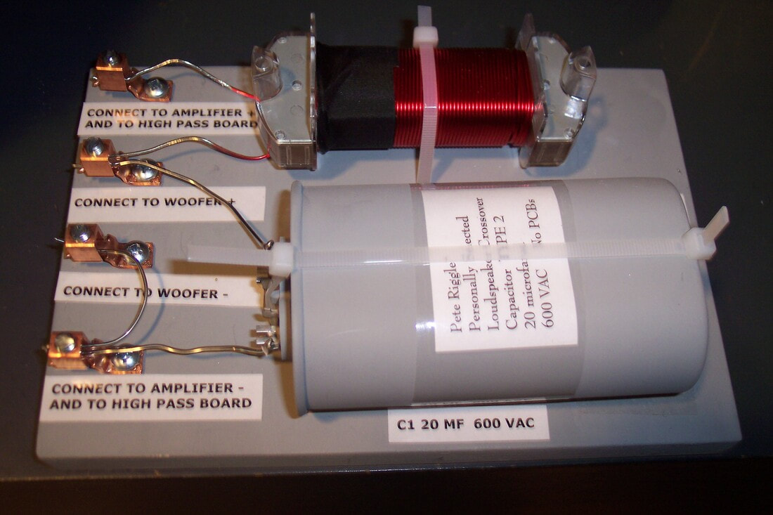
before adding front and rear panels to the crossover boards, I was securing all connections and controls to the bottom board. Images of some of these crossover networks can be seen below. The first group of photos is for Hiraga circuit crossovers for Altec A5 and A7 speakers.
Current Version of the Hiraga Circuit Crossover:
The photos below are for a recent pair of Hiraga Circuit crossover networks, intended for a pair of 16 Ohm Altec Lansing A5 loudspeakers with 1505 tweeter horns. This nicely crafted pair of crossovers sets my new standard. These crossovers were ordered without a cover. Attractive wood veneered covers are available as an option. Trophy shop name plates, and labels for controls and terminals are also available as an option. See a testimonial regarding these crossovers. A recent change, not shown in the photos is the inclusion of separate bass amplifier inputs and treble amplifier inputs for those who wish to biamp. These inputs can be strapped together (straps included) for operation with one amp per channel.
The photos below are for a recent pair of Hiraga Circuit crossover networks, intended for a pair of 16 Ohm Altec Lansing A5 loudspeakers with 1505 tweeter horns. This nicely crafted pair of crossovers sets my new standard. These crossovers were ordered without a cover. Attractive wood veneered covers are available as an option. Trophy shop name plates, and labels for controls and terminals are also available as an option. See a testimonial regarding these crossovers. A recent change, not shown in the photos is the inclusion of separate bass amplifier inputs and treble amplifier inputs for those who wish to biamp. These inputs can be strapped together (straps included) for operation with one amp per channel.
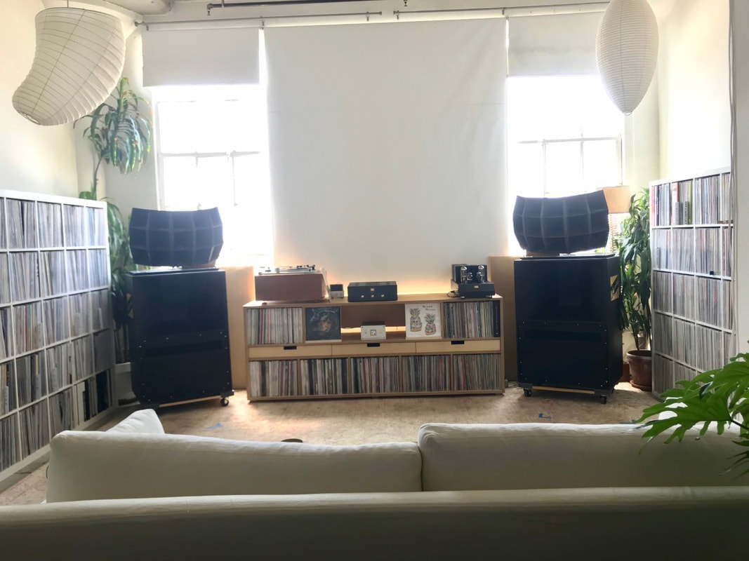
The photos below show the Altec Lansing A5 loudspeakers that the above 16 Ohm Hiraga circuit crossovers are being used with. You can see the crossovers peeking out from behind the Altec 1505 tweeters.
Pete Riggle Audio
2112 S. Olympia Street, Kennewick WA 99337, USA
shop phone: 509 582 4548 email: [email protected]
VTAF™ Trademarked. U.S.Patent No. 7630288.
Website content Copyright © 2021 Pete Riggle Audio, All Rights Reserved.
2112 S. Olympia Street, Kennewick WA 99337, USA
shop phone: 509 582 4548 email: [email protected]
VTAF™ Trademarked. U.S.Patent No. 7630288.
Website content Copyright © 2021 Pete Riggle Audio, All Rights Reserved.

